
After watching a plush toy hatch theatrically out of an egg, I was about to throw away the leftover plastic − as is typically intended. But there was still some electronics inside, so I fiddled with it for a while, but found nothing worth keeping.
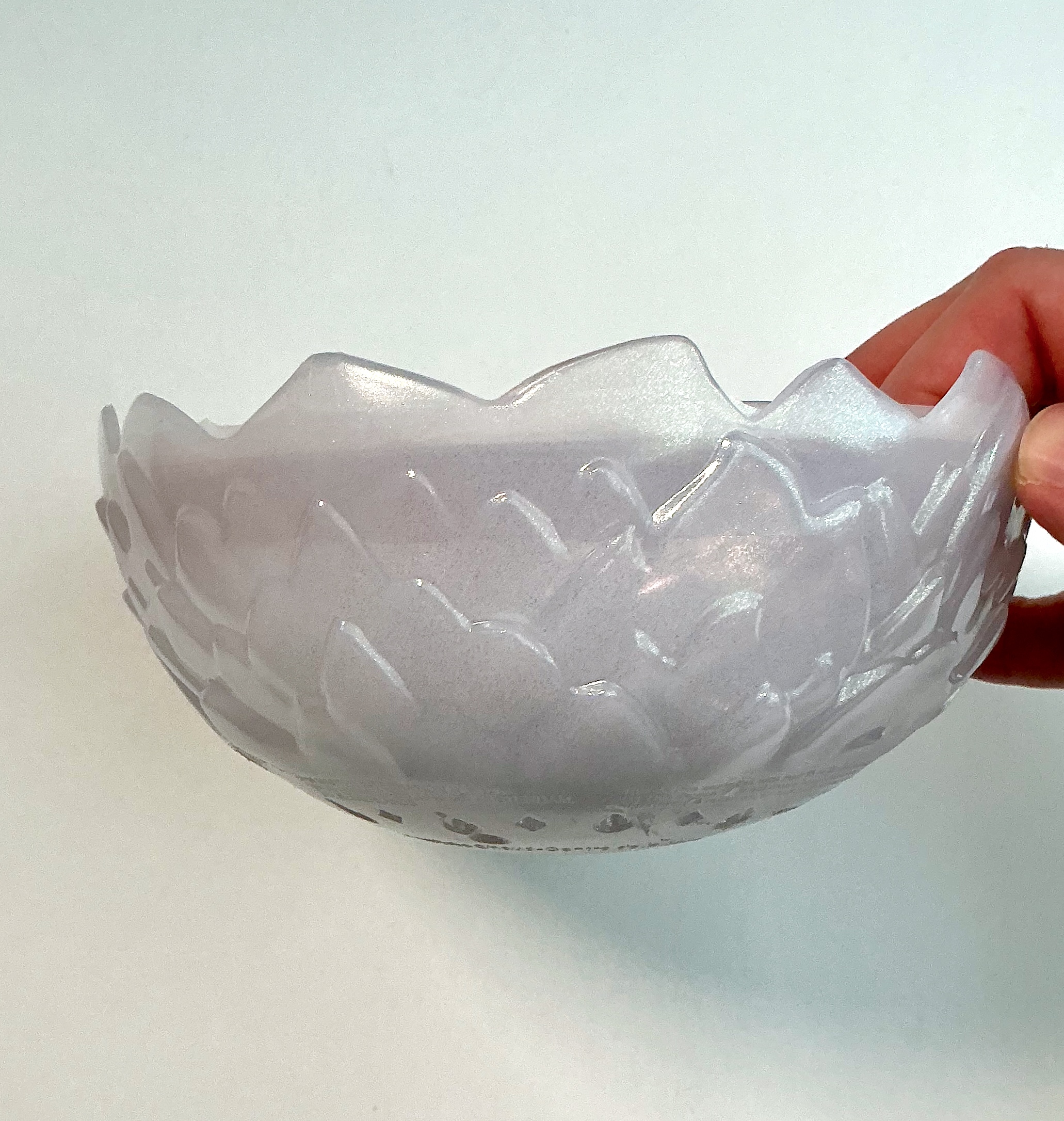
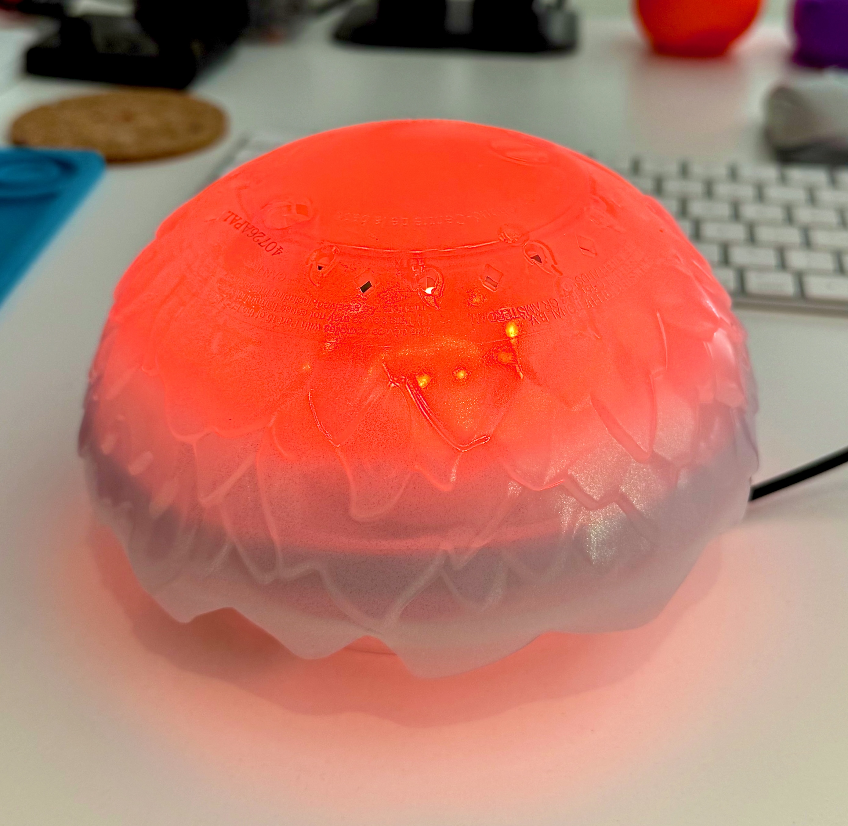
The shell was another matter. It’s already a diffuser, and it splits into two halves – one could make a stand, the other a top. That’s most of a table lamp already, so I decided to make a little project out of it.
1. The lamp
The functional requirements for the lamp were as follows:
- Nice glow and the ability to use different colors
- No switch or app as the primary control plane: touch the shell, colour changes
- Powered from a USB-A or -C, to make it easy to find power source.
- Must fit into the “case” (egg leftovers)
2. Parts
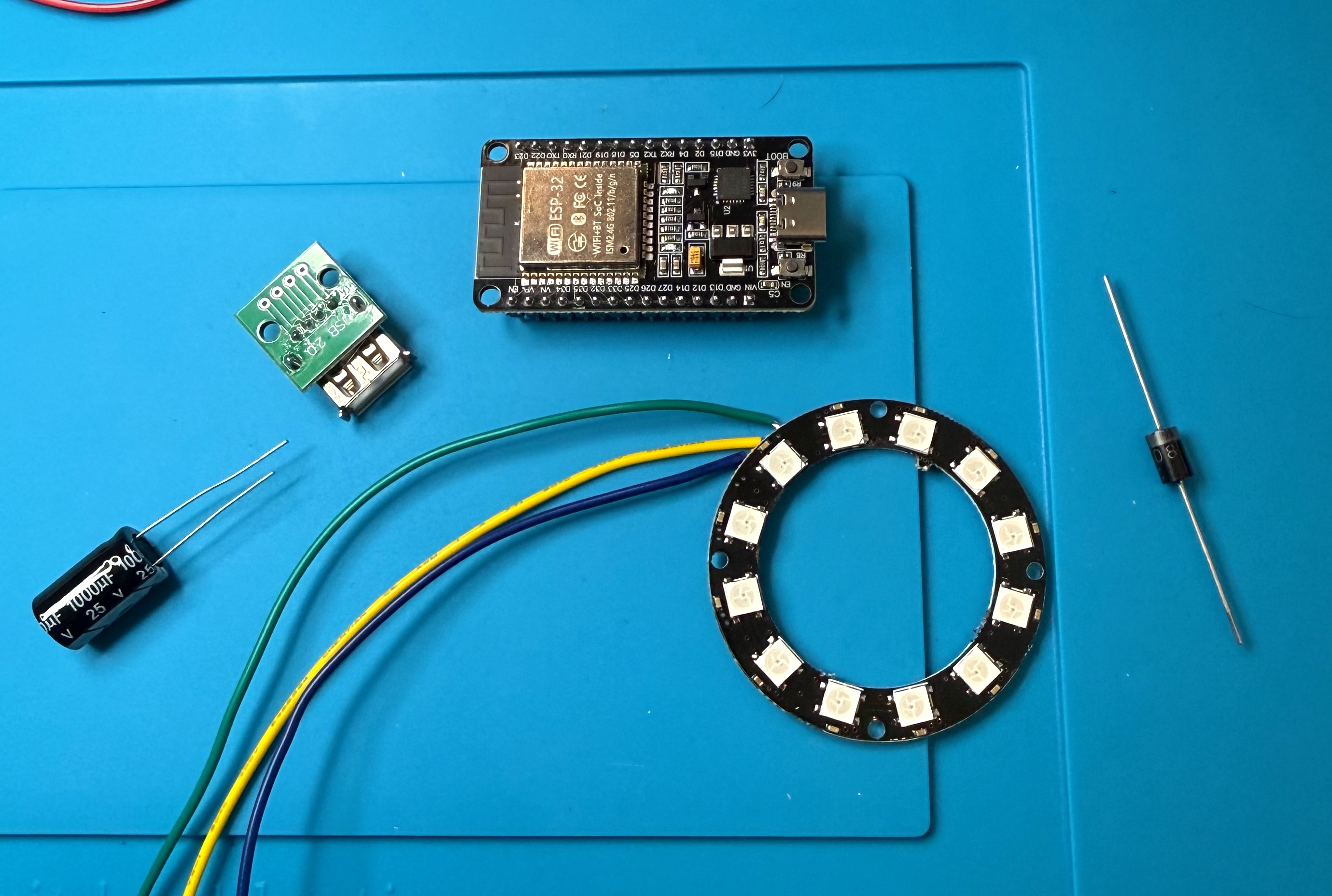
- AWG-22 wires, shrink-wraps, small tie wraps
- ESP32-WROOM-32. Needs to respond to capacitive input (touch), so not a C3/C6/H2 version
- WS2812 ring: addressable, needs only three wires, and small enough to sit in the base. I went with a 12 LED one
- 1N5408 diode to make WS2812 signaling work well
- 470 Ω resistor on the data line: to damp reflections and protect the first pixel’s input during power-up
- USB-A screw terminal breakout (that I ended up not using)
- Copper tape pad. Already glued to the egg base − that’s how the toy knows it’s being held before hatching starts
- Hot glue gun to fix things in place. What a wonderful appliance!
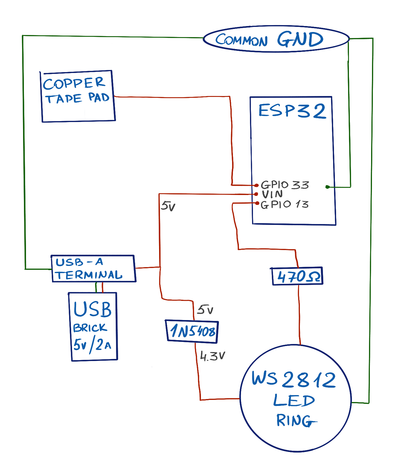
- Standoffs for the ESP32 to fix it in place
- a 1000 µF capacitor to smooth out the WS2812 power. Ended up not using it because for a ring of just 12 LEDs it wouldn’t add much anyway.
3. Ring’s 0.7 × VDD problem
The WS2812B ring wants a logic high above 0.7 × VDD. “Logic” in this case is the signal from ESP32 that tells the LEDs what to do. At 5 V that’s 3.5 V.
ESP32 GPIO puts out 3.3 V, so we’re 200 mV short. It usually works, but then the wire gets longer, or the room gets cold, and it doesn’t and it’s hard to debug.
One of the options was a 74AHCT125 buffer – a good solution, but I couldn’t find the chip and it would have been tricky to mount it. Another one was a silicon diode in the ring’s 5 V line (1N5408), dropping VDD to about 4.3 V, which drags the threshold down to ~3.0 V. That would have provided 3.3 V output, now with 300 mV of nice margin instead of a 200 mV deficit.
4. Wiring diagram
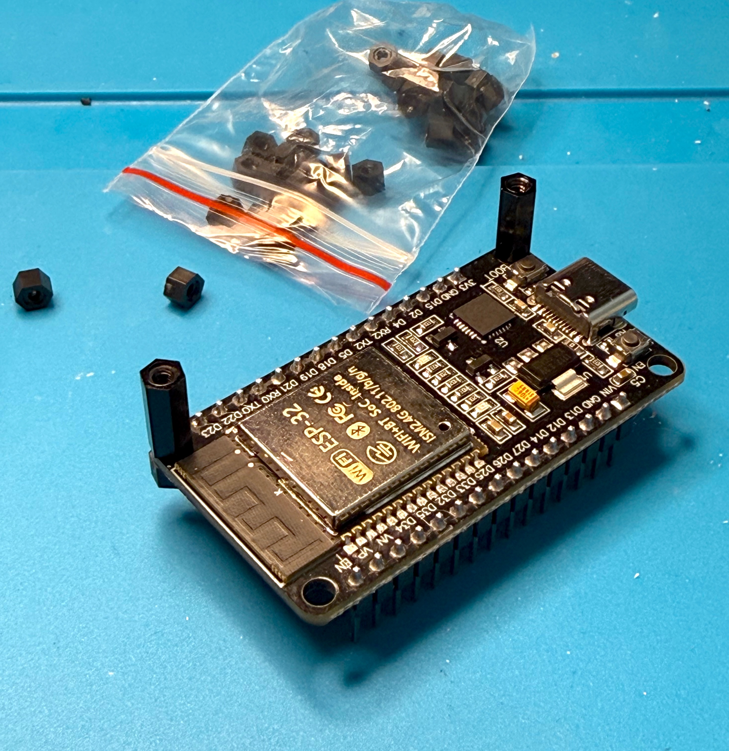
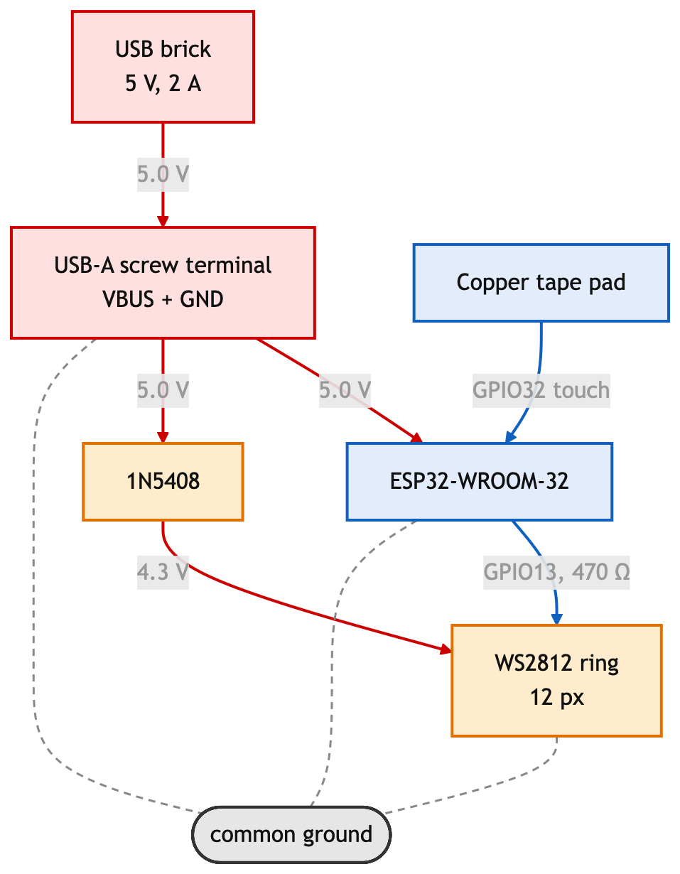
A quick sketch of the wiring diagram: a 5 V USB brick feeds a USB-A terminal, whose 5 V rail branches to the ESP32 VIN and through a 1N5408 diode to the WS2812 ring, giving it 4.3 V.
GPIO 13 drives the ring data line through a 470 Ω resistor, GPIO 33 goes to the copper tape pad, and a common ground net ties everything together.
5. Building it
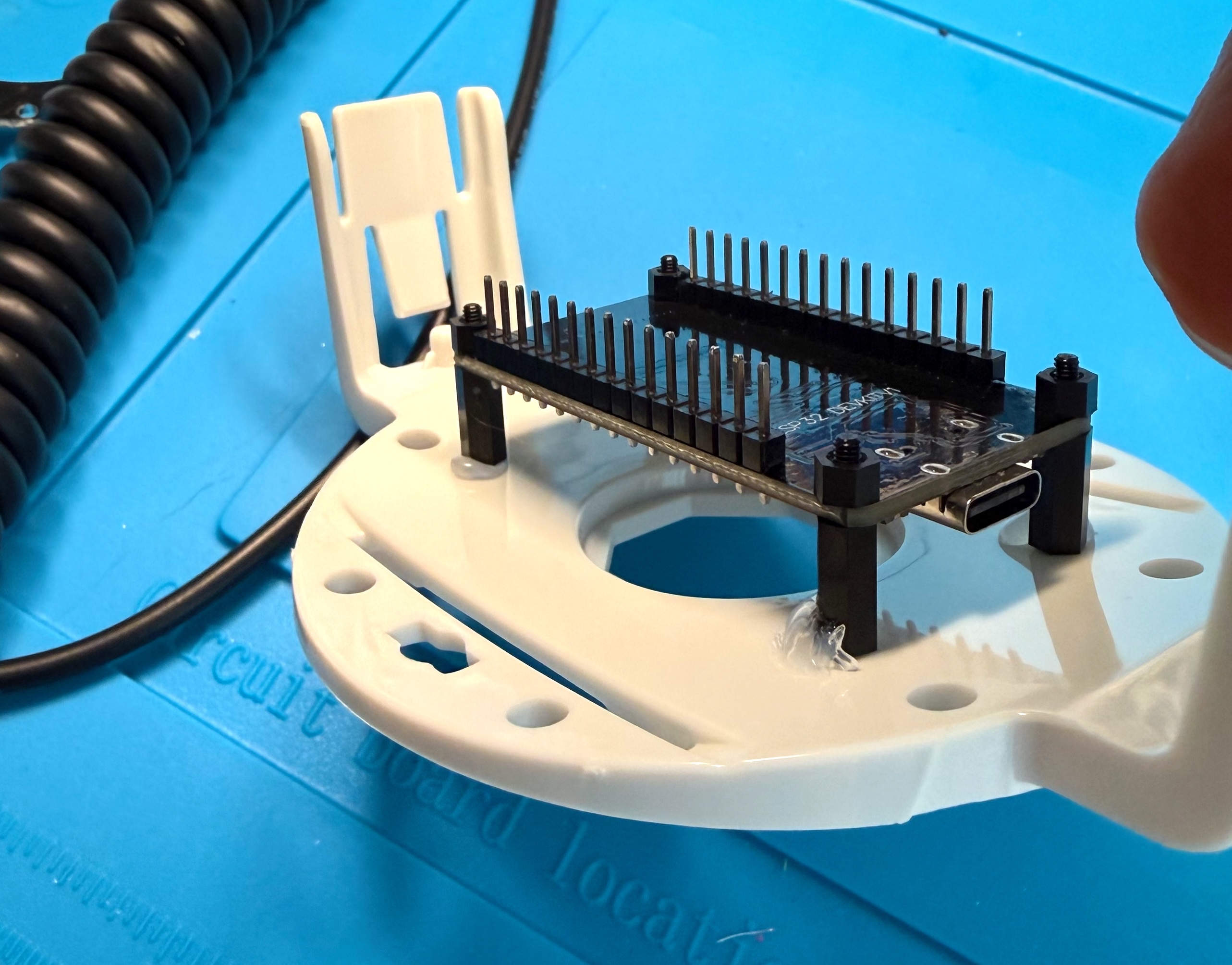
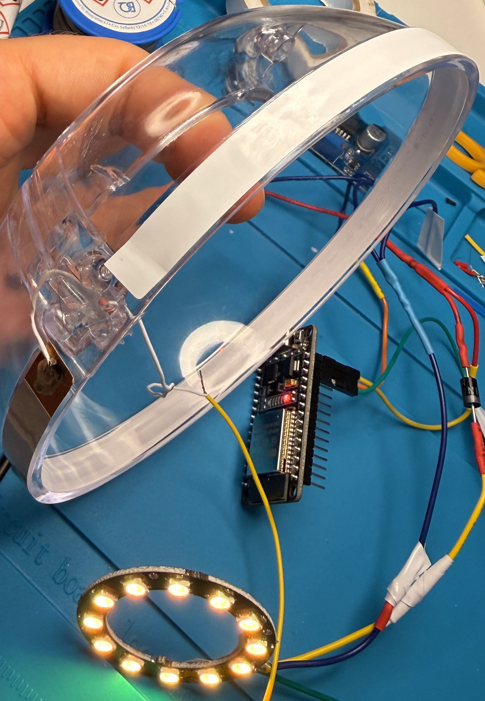
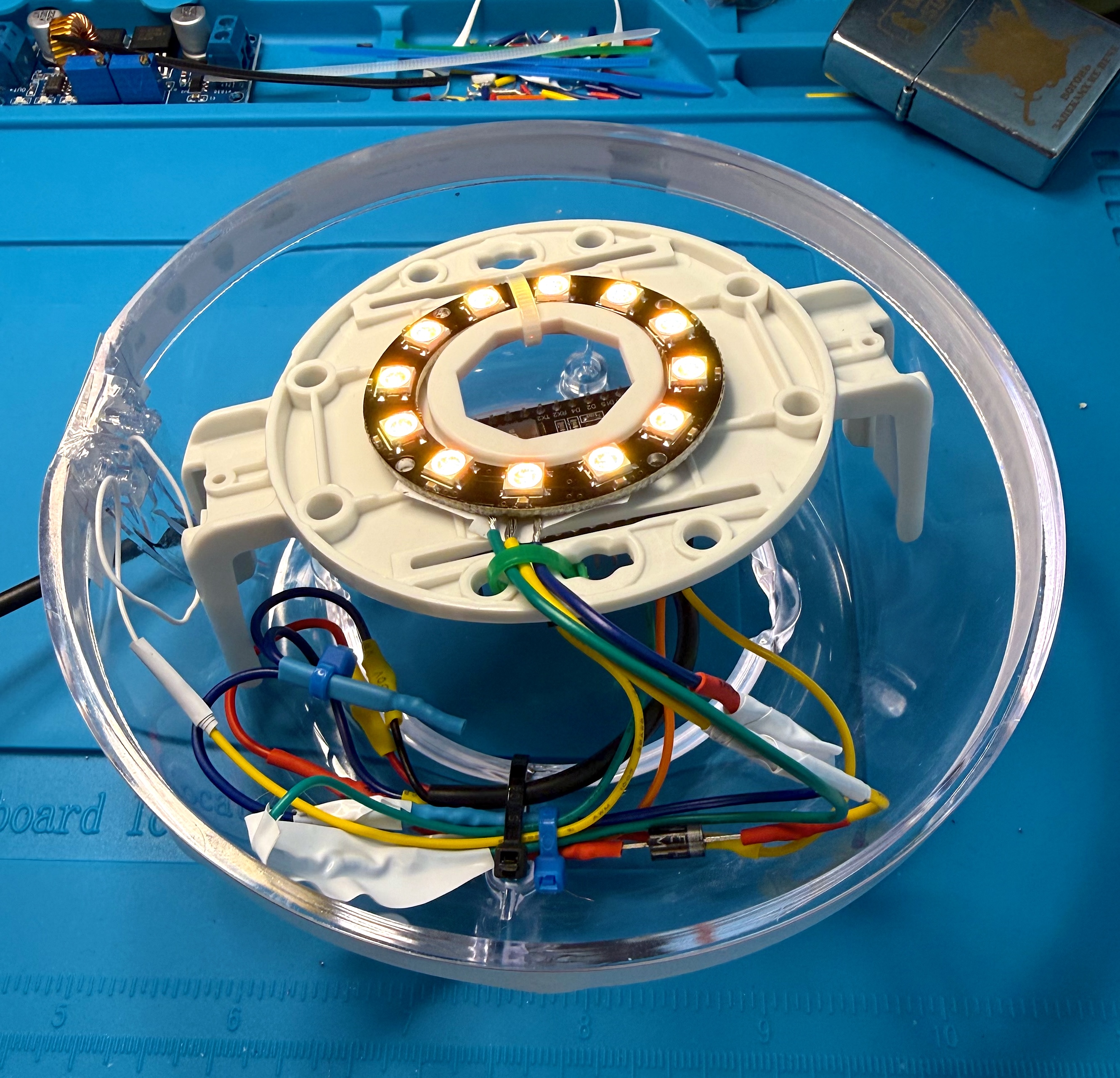
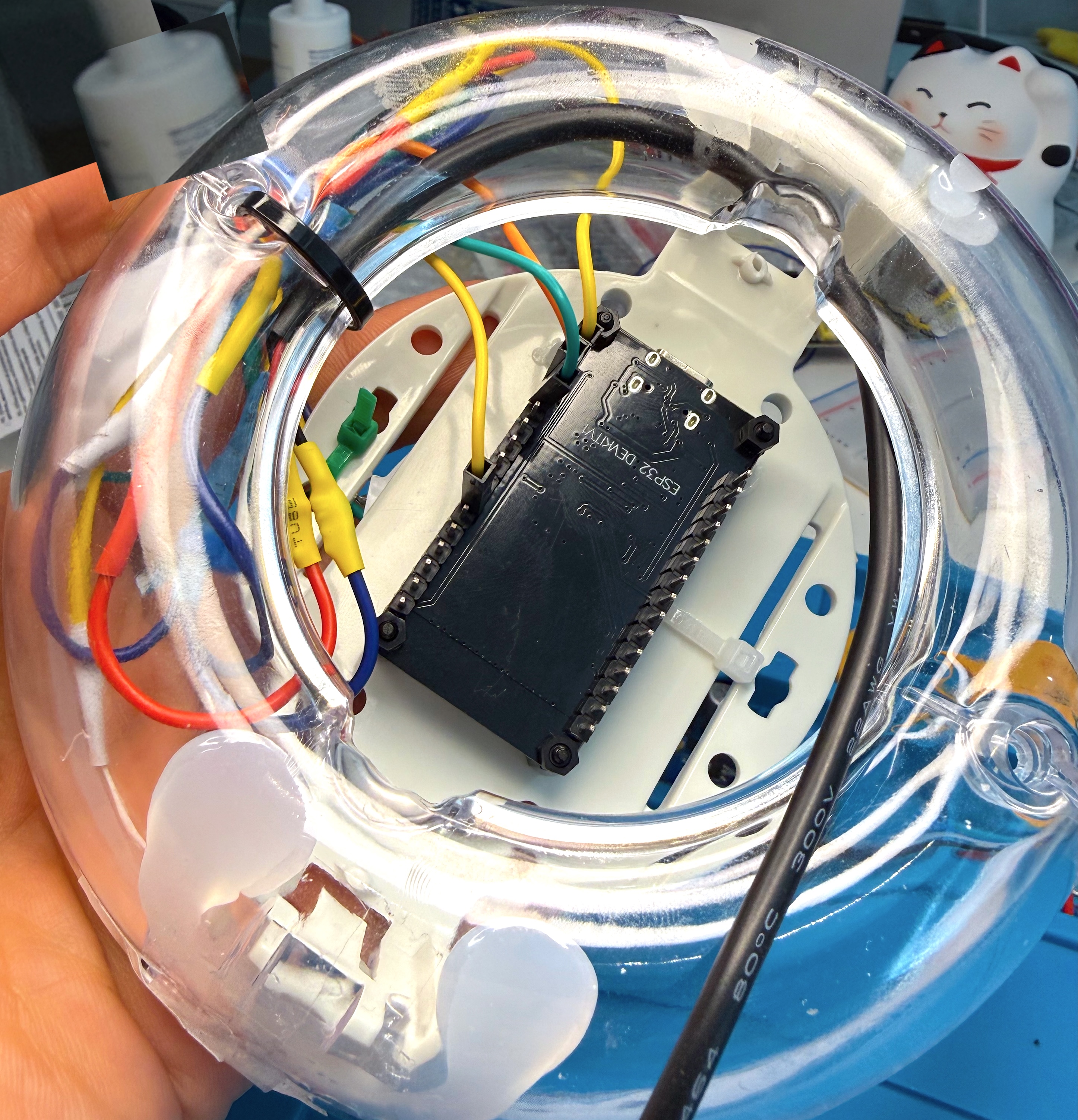
6. Then nothing worked
When I powered it up, nothing happened 🥺 Alright then, let the debugging begin!
The little LED on the ESP32 board was flickering, suggesting a brownout loop. One second of light, dark, repeat. So I split the circuit, tested each half, then each component. Every part passed individually.
Diode good on the multimeter, ring good on its own, board good on its own. Assembled: brownout.
The €1 USB breakout is the one that deserves a little swear word. Unloaded it read a perfect 5.0 V. Under a 330 Ω test load it read 3.3 V. That’s 10 mA and 1.7 V missing, which is about 170 Ω of series resistance somewhere in a path that should be well under 1 Ω!
Nothing legitimate in a USB path is 170 Ω 🫤
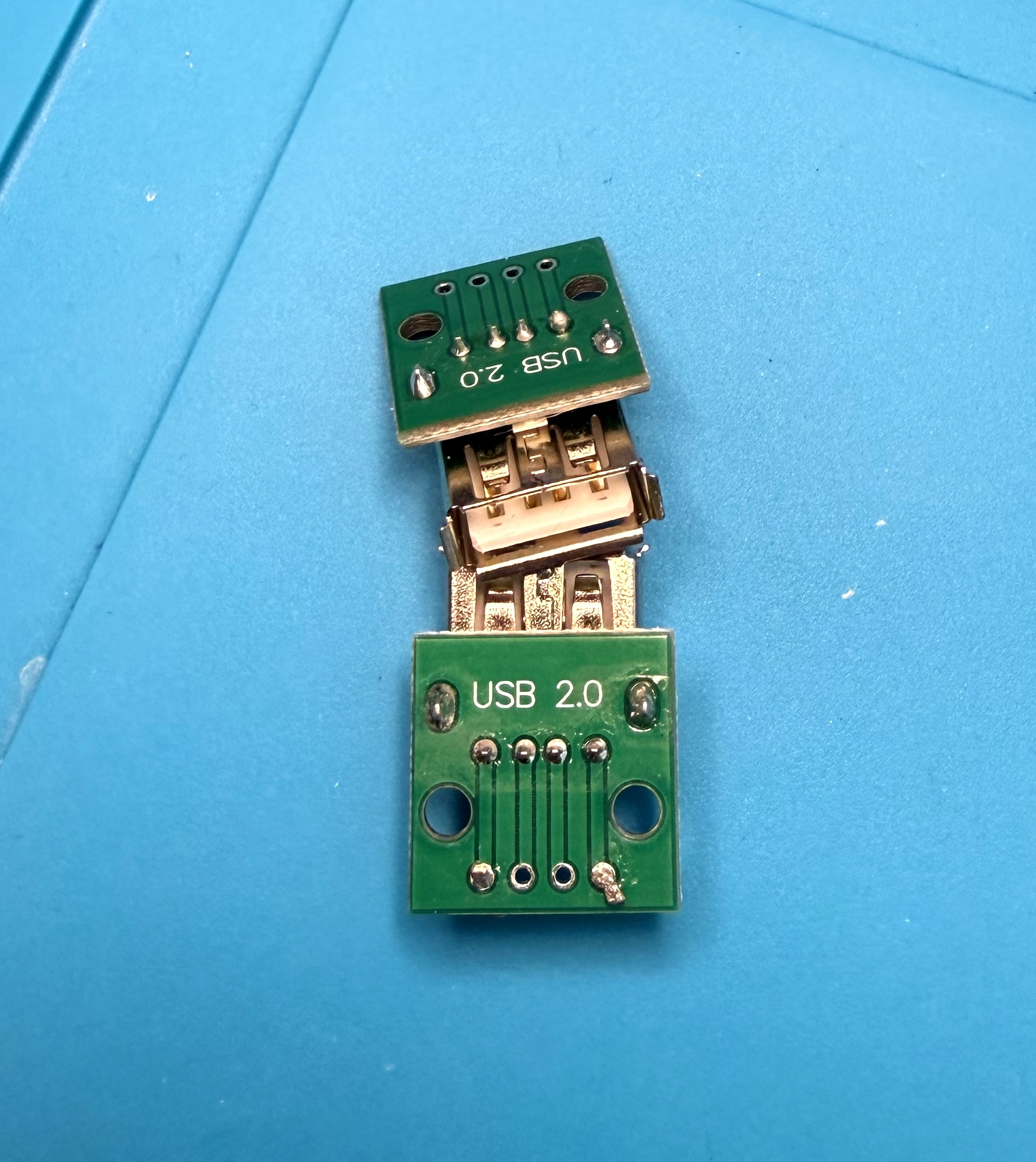
I still don’t know what was the exact problem there, likely a cold joint on the connector’s VBUS leg – the shell tabs soak up heat during factory reflow and the leg ends up tacked in flux rather than wetted. Or a thousand other possible reasons.
A multimeter with a 10 MΩ input draws half a microamp, and at that current, 170 Ω is invisible. You get a phantom 5 V, so testing under load is a quick way to find out. Took me hours to understand that, though.
After replacing the breakout with another one that looked like a finished USB cable with 2 wires, it worked.
7. Software and the touch behaviour
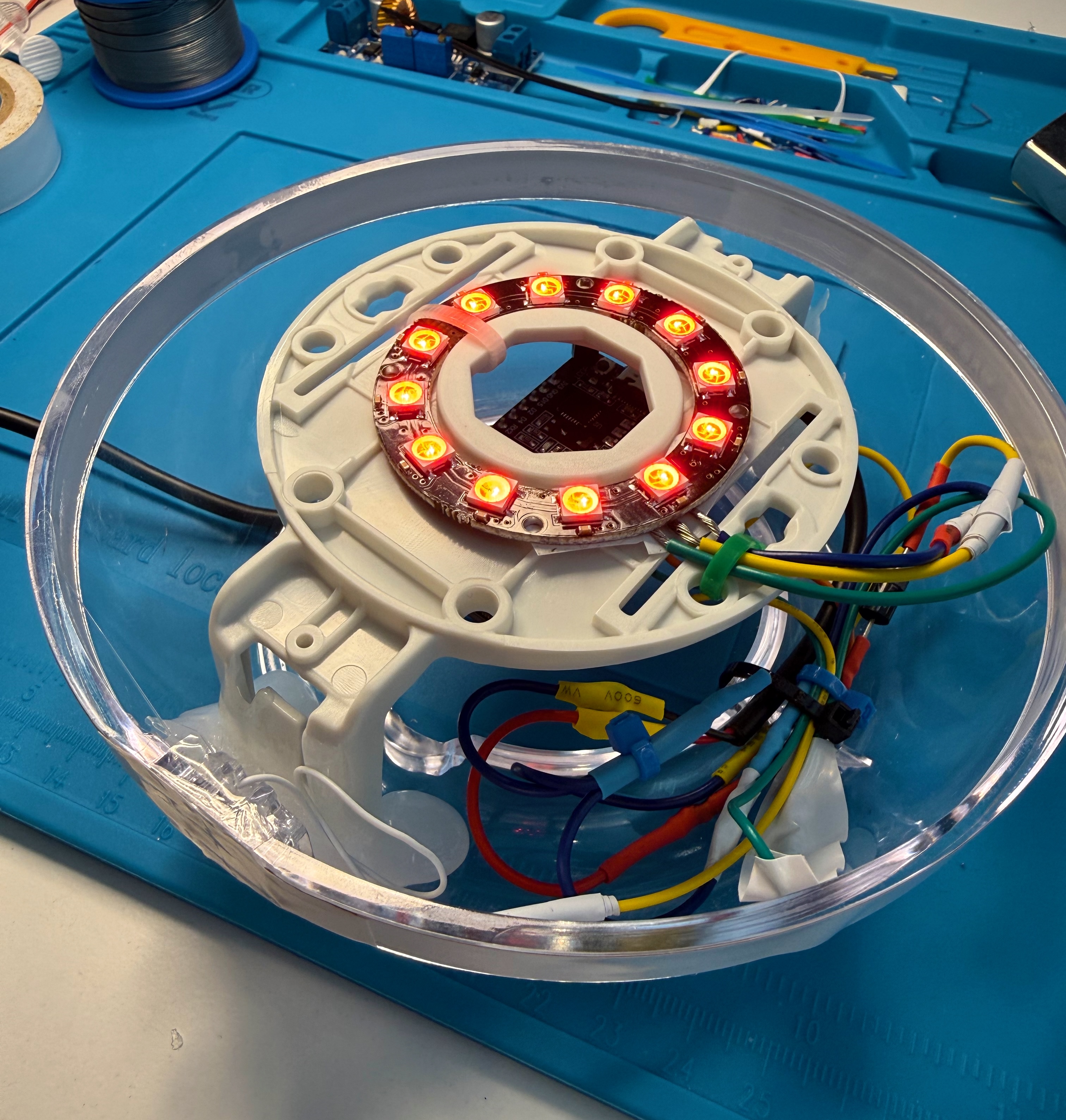
To make the lamp do something when touched, I created 8 WLED presets and bound touch as a button, {"ps":"1~8~r"} to jump to a random preset in the range + transition time set so it fades instead of snapping.
8. Wiring reference
All in all, a nice and fun weekend project. Cost was about €15 and 2 evenings, one of which was spent on a connector.
Thanks for reading, and happy hacking!