
An optocoupler is a part I’d seen in schematics for a while and quietly skipped over. There’s an LED pointed at a photo-sensitive transistor with a dashed line between them. The dashed line is the entire point: the two halves of the part are not electrically connected.
The signal crosses as light, over a few hundred microns of darkness – and I wanted to see it work! So I built one on a breadboard before reaching for an actual 4N35 chip.
This post is what I learned along the way. Enjoy!
1. What an optocoupler is
An optocoupler (or opto-isolator) is a single component with two electrically separate halves:
- Input side: an LED. Driven like any other LED.
- Output side: a phototransistor that conducts when it sees light from that LED.
The two halves share a package, but not an electrical path. The signal crosses as ✨photons✨, over a tiny air or epoxy gap. The gap is the whole point of the part.
A few common reasons to use one:
- Galvanic isolation. Voltage spikes, ground loops, or accidental high-voltage events on one side don’t propagate to the other. Industrial controllers, medical devices, and anything touching mains power lean on this a lot.
- Voltage-domain bridging. A 3.3 V microcontroller can drive a 24 V industrial input without either side seeing the other’s reference.
- Noise rejection. No conductive path means no shared ground, which kills a whole class of noise problems before they start.
The schematic symbol makes the architecture easy to understand:
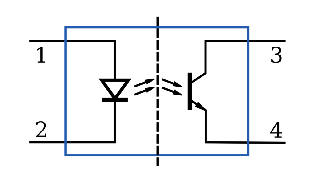
LED on the left, phototransistor on the right, dashed line through the middle showing the isolation barrier.
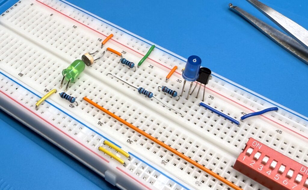
2. Building one from discrete parts
- Lower half is the “transmitter”: green LED + 220 Ω current-limiting resistor + a DIP switch acting as the on/off control. Wiring:
5V → green LED → R4 (220Ω) → DIP switch → GND - Upper half is the “receiver”: LDR pulled up to 5 V, a 2N2222 transistor, and a blue indicator LED that lights when the transistor conducts. Wiring:
5V → LDR → SENSE node → R1 (2kΩ pull-down) → GND
SENSE → R2 (22kΩ) → T1 base
5V → R3 (220Ω) → blue LED → T1 collector
T1 emitter → GND
The LDR forms a voltage divider with R1. In the dark, the LDR’s resistance is huge, so SENSE sits near ground.
With light hitting it, the LDR’s resistance plummets, SENSE rises, current flows through R2 into the base of T1, and the blue LED on the collector lights up. Classic NPN switch driven by a photo-sensor instead of a button.
R1 isn’t strictly required, but without it SENSE floats too high in the dark and the transistor never fully turns off.
Isolating it from room light
The whole experiment falls apart if ambient light leaks onto the LDR. So I put a low-tech opaque cap over the LDR + green LED area to make a tiny dark chamber:
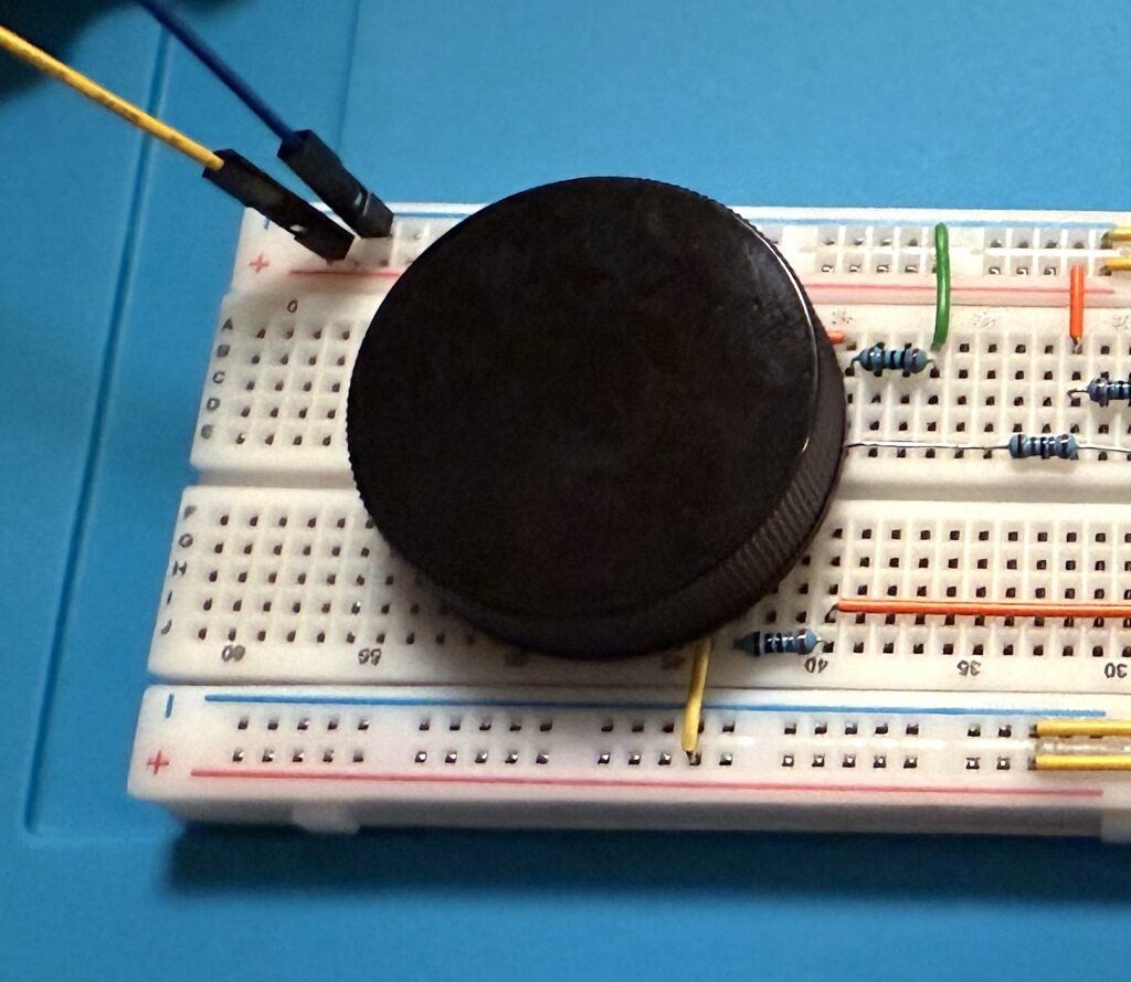
Inside that cap is the entire “channel” between the two sides of the circuit.
No copper in there − again, just ✨photons✨.
Measurements
With the cap in place and the green LED off (DIP switch open), here’s what the SENSE node reads:
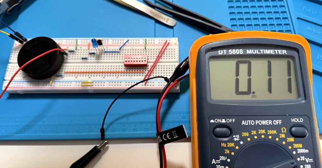
SENSE0.11 V is well below the 2N2222’s base-emitter turn-on threshold, so the blue LED stays dark. Base current measured at 0.00 µA on the 20 µA range − effectively zero.
Now let’s flip the DIP switch. Green LED on, light hits the LDR through the dark chamber, LDR resistance collapses:
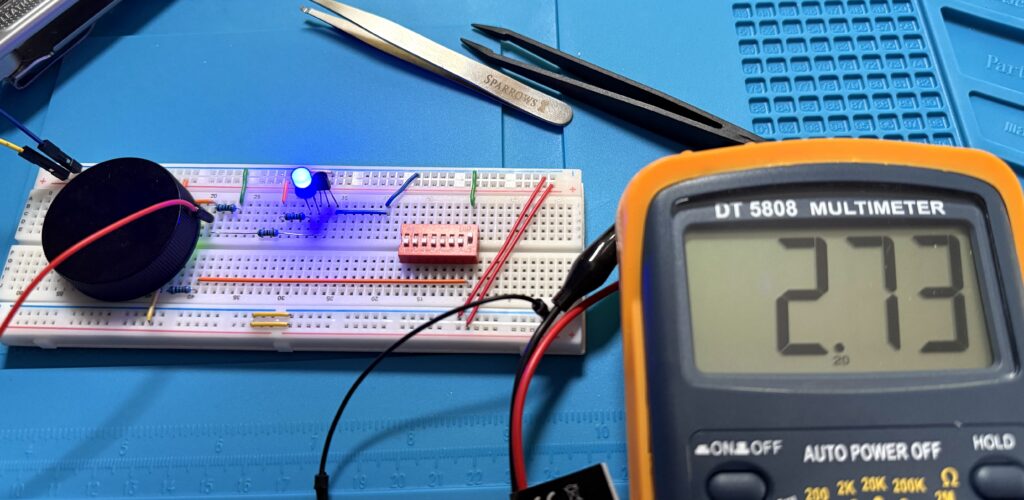
SENSE2.73 V at SENSE. Plenty to drive the base. Base current jumps to 0.07 mA on the 20 mA range − about 70 µA, enough to switch the 2N2222 on for this little indicator circuit. And the blue LED lights up 🔵
That’s roughly what’s happening inside a basic transistor-output optocoupler: light in, switching action out, no electrical connection between the two halves.
Here’s a little demo:
3. Replacing the build with a 4N35
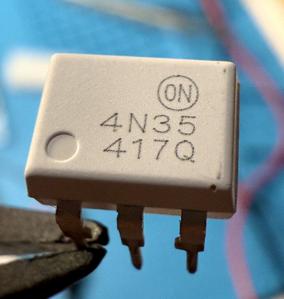
The discrete version works, but it’s huge and very photosensitive in the wrong way. Time to swap it for the real thing: a 4N35, a through-hole optocoupler with an IR LED on one side and an NPN phototransistor on the other, all packed into a 6-pin DIP.
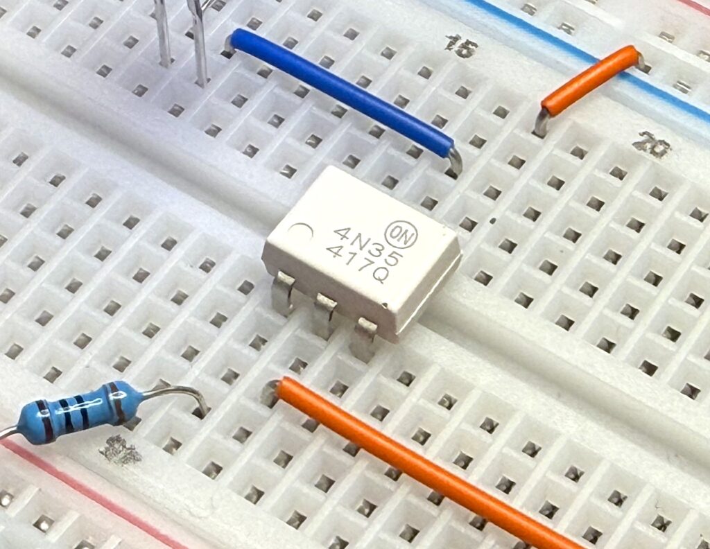
Same job, much less real estate. The 4N35 (the small white DIP labeled 4N35 417Q) replaces:
- the LDR,
- the green LED,
- the dark chamber,
- the 2N2222,
- and the 2 kΩ pull-down
basically half the previous breadboard. The blue indicator LED still lights when the input side is driven, exactly as before.
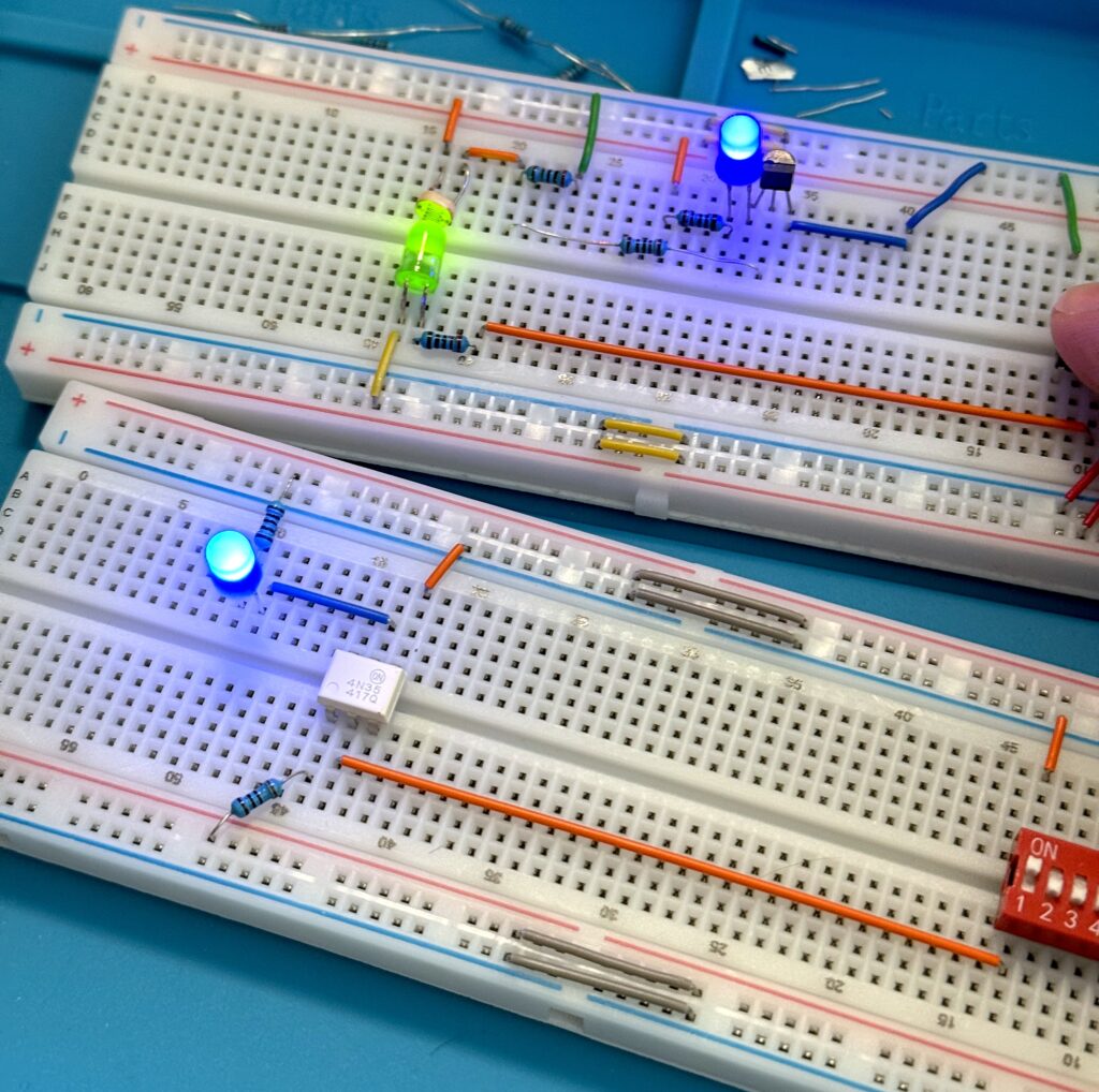
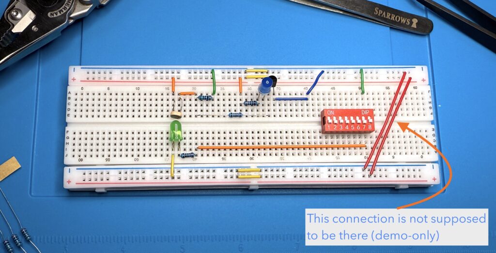
Both builds running, side by side:
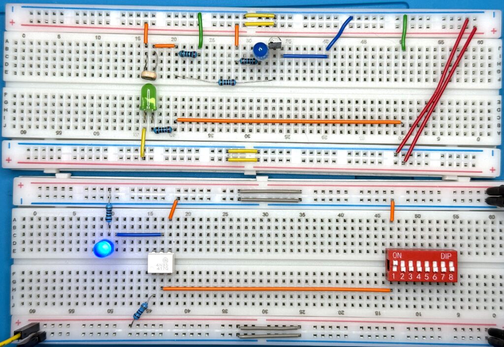
The bottom board is the new build with a 4N35; the top board is the original LDR contraption, kept around for comparison.
Why the chip wins:
- No ambient light problems. The IR LED and phototransistor live in a sealed opaque package. No improvised dark chamber required. It’s as dark as it gets in there.
- Predictable performance. The datasheet specifies a minimum current transfer ratio (CTR) of 100% at I_F = 10 mA, a forward voltage of 1.20 V typical, and turn-on/turn-off times around 10 µs. The discrete version specifies “depends on what LDR I had in the drawer”.
- Real isolation. The 4N35 is rated for 5,000 V AC RMS isolation
*between input and output for one minute. My breadboard build is rated for “until something arcs across the rails”. - Smaller and faster. A 4N35 takes 6 holes on a breadboard and switches in microseconds. An LDR’s response is more like tens of milliseconds − three orders of magnitude slower.
So: building one is how I understood it. The chip is what I’d actually use.* This does not make a breadboard safe for mains experiments.
4. Where optocouplers show up
After the breadboard experiment, I went looking for where optocouplers actually get used. A few common ones:
- Switch-mode power supplies. Laptop chargers, ATX supplies, USB-C bricks − most use an optocoupler to send the regulation signal from the secondary side back to the primary controller, across the isolation barrier.
- Industrial I/O. PLCs and motor controllers use optocouplers on every digital input. A 24 V signal from a sensor enters through an opto and comes out as clean 3.3 V or 5 V logic.
- MIDI. The standard MIDI input circuit specifies an optocoupler (typically a 6N138). It’s how synths from different manufacturers, with different power supplies, can be daisy-chained without ground loops humming through the speakers.
- Solid-state relays. An SSR is essentially an optocoupler driving a triac or MOSFET. A few mA into the input LED switches hundreds of volts on the output. No mechanical contacts, no arcing.
So anywhere a low-voltage logic world needs to talk to a higher-voltage, noisier, or legally-requires-isolation world, there’s probably an opto in there.
Summary
Optocouplers are a small, elegant idea: send a signal as light, get it back as a switch, without ever sharing a wire. Building one from an LED, an LDR, and a transistor is what made it click for me. Replacing it with a 4N35 made the case for the chip click just as fast.
A lot of components that look like magic are doing something simple, packed tightly. This one is just an LED pointed at a phototransistor. The work is being done by a few hundred microns of darkness. Amaze! ✨
Thanks for reading, and happy hacking!